BMW Ellipsoid install

Forum rules
All advice given here is advice from persons using these forums,these opinions are not of the websites owners,and must be used at own discretion.
nwdatsuns does not verify the accuracy of given advice

This section is for informational How to's
Including, how to on datsuns, general technical, fabrication, electrical etc. Not limited to those, but for real information.
The how to make eggs and sammiches should go under General Discussion, as those topics aren't indexed for searches.
Post Reply
User avatar
Laecaon
Site Admin
Posts: 4787
Joined: Wed Jun 26, 2013 7:21 pm
Cars: '71 510 Wagon, 02 BMW 325i Wagon
Location: PDX, West side.
Has thanked: 288 times
Been thanked: 329 times

BMW Ellipsoid install

#1

Post by Laecaon » Thu Jun 27, 2013 8:27 pm

After getting my ellipsoids I really wanted to get them in. After looking through all the installs I could find on the forum, I felt that I could wing it. This is for the people who dont feel that they could wing it. This is for the H1(HB4) bulb ellipsoids.

Wiring for the lights are in the second post.
521 wiring is at the end of post 2


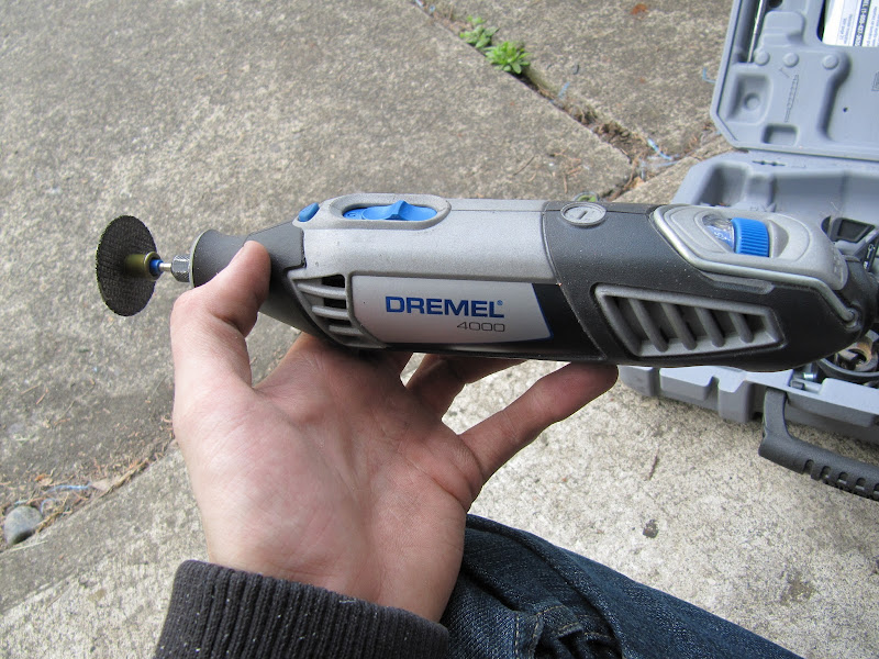
The following tools greatly sped up things:
Image
Image

Pliers,
Screw drivers,
Electrical connectors and crimping/stripping tool,
Hammer,
Soldering Iron if you feel like it (I did),
any other miscellaneous tools you find can help you

Supplies:
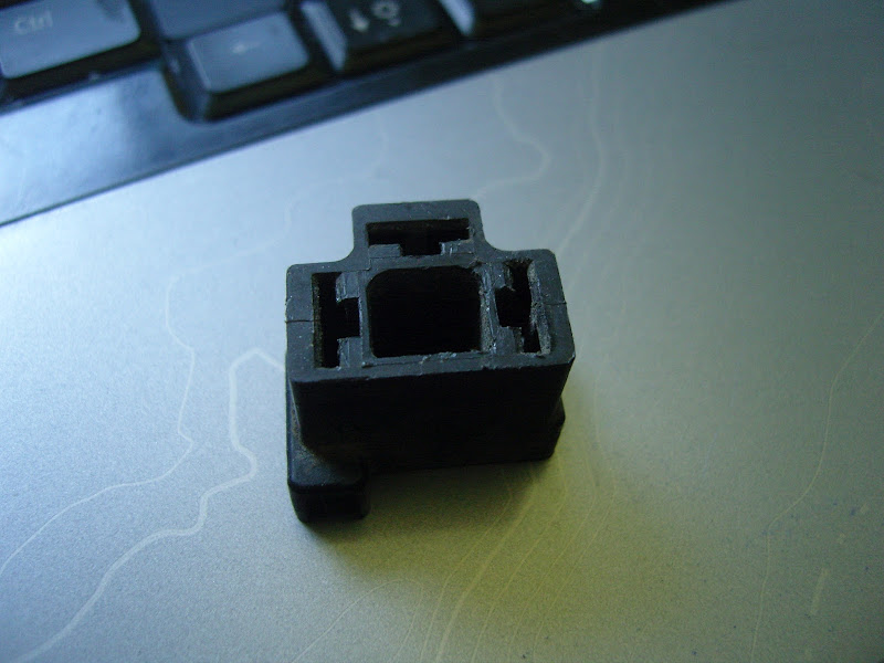
Ellipsoids, bulbs, plug for the lights (I used the BMW ones, but any 9006 bulb connector will work)
Electrical Connects as mentioned above:
ImageImage
12 Gauge wire (I grabbed a 10 foot section)
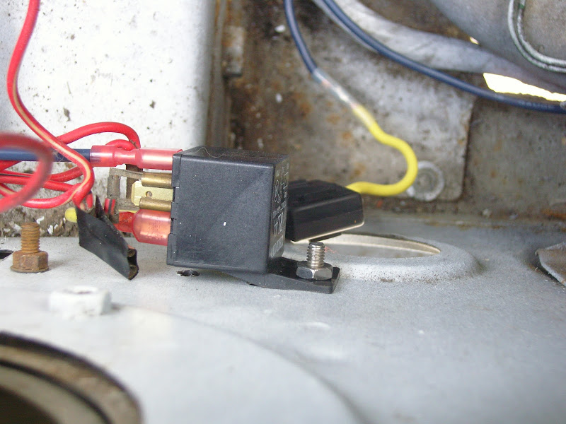
2 Relays of at least 30 amp (Must have pins 30,85,86,87)
Image
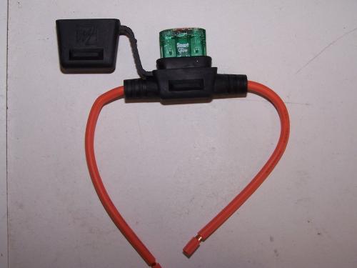
Inline fuse holder and fuse (I used a 30 amp fuse, this may be too high to properly protect the system)
Image

The fun stuff!
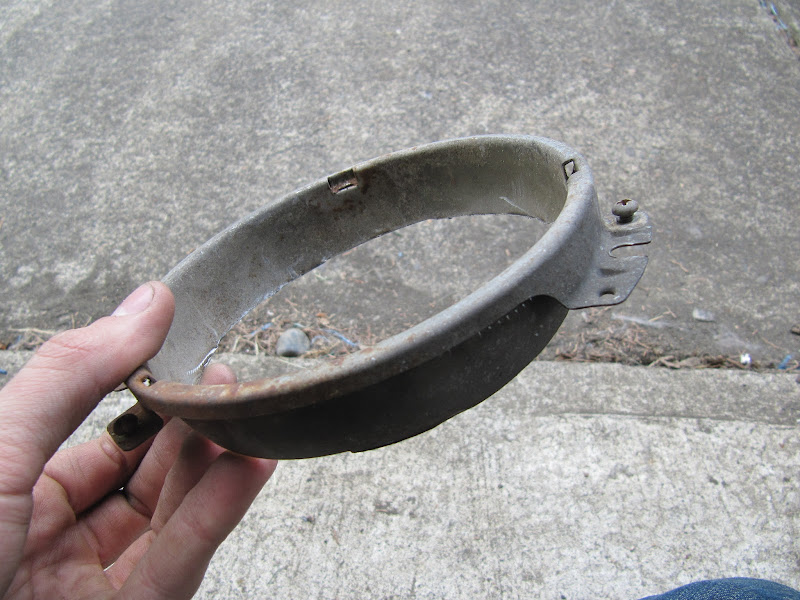
Take out all your headlights/brackets. Remove the cups for the low beams. I then cut 1 inch from the front of the front the cups to make them look like this:
Image

Next step is to remove the Chrome rings from the ellipsoids. Then to shave down the tabs to the following, This is where the dremel was most useful.Bit of trial and error in this, make sure to shave all the way through.
Image

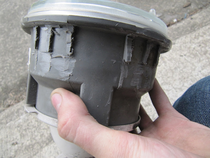
Then slide the cup onto the ellipsoid and screw the retainer ring done.
Image

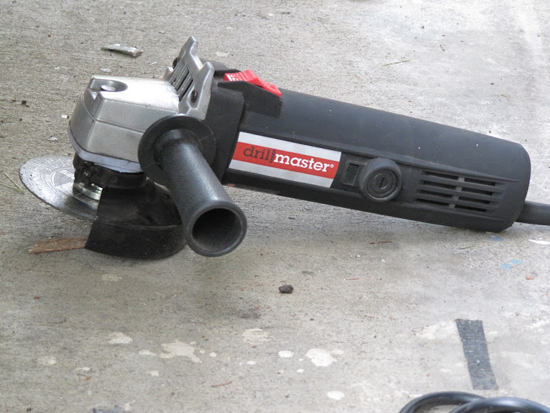
Next we need to modify the bracket that holds the lights. Angle grinder to the rescue! From this:
Image
to this:
Image


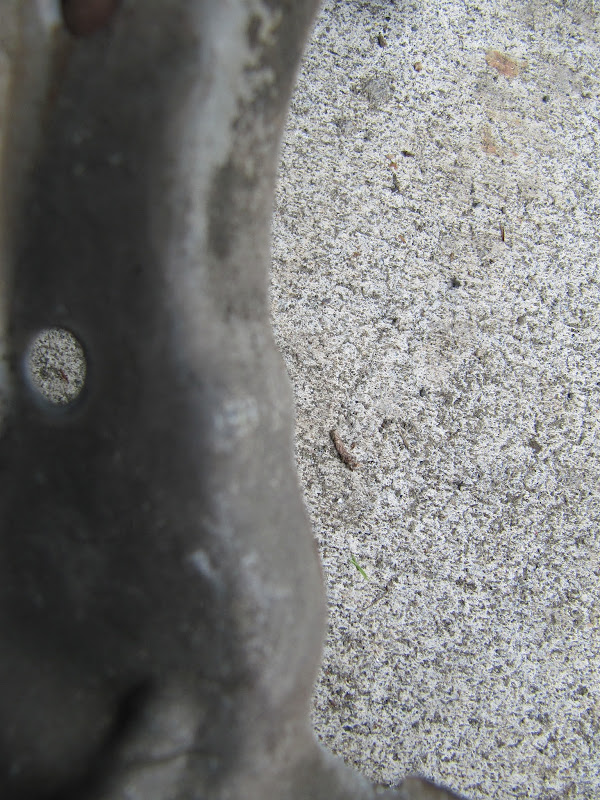
I ran into a clearance issue with one of the bumps on the bracket obstructing the ellipsoid, this is the bump:
Image

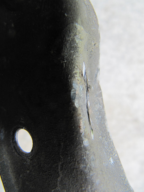
I then cut a slot in the bump and hammered it smooth:
Image

Finally reassemble the headlights back together. I might add, make sure when installing the lights into the buckets you get the orientation correct.
Image

Next step is to hammer the inner fenders for clearance. I had to cut the washer fluid bracket. Hard to tell how much I hammered it, but not a whole lot, and it goes with the lines already on the inner fender:
Image

Now you headlights should be able to fit on the car.

User avatar
Laecaon
Site Admin
Posts: 4787
Joined: Wed Jun 26, 2013 7:21 pm
Cars: '71 510 Wagon, 02 BMW 325i Wagon
Location: PDX, West side.
Has thanked: 288 times
Been thanked: 329 times

Re: BMW Ellipsoid install

#2

Post by Laecaon » Thu Jun 27, 2013 8:27 pm

Ok, on with the wiring! Everyones favorite part, actually it was my first step.

I did this twice, 1 for each side.

Here is the wiring Diagram I am using: (Full size image found here: http://flic.kr/p/9TRUxj)
Image


First step, disconnect the battery!

Grab the connector for the low beams. We are going to pull all the leads out of it. It will look like this:
Image
To pull the connectors out I had to slip in a thin piece of metal into the notch in each slot.

On the 510 Harness, Red with Black (RB) is ground for the Low beam light. You will plug RB into the 85 terminal. The passenger positive wire is Red (R) while the driver side is Red with Blue (RL). Depending on the side of the car you are working on you will plug either one into the 86 terminal on the relay. You also have a set of wires, Red with White (RW). Wrap the end of the RW with electrical tape, this is the ground for the high beams. You should be done with the 510 harness now.
Image

Now for soldering and crimping!

I first ran my positive wires. I decided to grap my power from the positive terminal on the starter solenoid.
Image

At the other end of the wire I soldered my Inline fuse and placed the heat shrink over it. Added a female spade connector and plugged it into the 30 terminal on the relay. Here you can see the fuse holder:
Image

Grabbed the harness from the BMW lights and did some soldering. Brown is ground, and Yellow with blue is Positive.
Image
I ran the brown wire to a close screw for ground. The other end of the positive wire runs to the 87 terminal on the relay.

Finally I mounted the relay to the core support by a screw I had holding in my valence. Plug everything in and install your headlights if you have not yet.

All done!
Image

~~~~~~~~~~~~~~~~~~~~~~~~~~~~~~~~~~~~~~~~~~~~~~~~~~~~~~~~~~~~~~~~~~~~~~~~~~~~~~~~~~~~~~~~~~~~~~~~~~~~~~~~~~~~~~~~~~~~~~~~~~~

So here is the new diagram, with proper colors for the 521.

Image

Some quick differences between the 510 and 521:

Basically the differences between the 510 and 521 are that the 510 is ground switching and the 521 is positive switching.

The 510 has separate + power to each side of the car for lights (including 2 fuses, 1 for each side). The 521 shares a common positive, and a ground.

On my install on the 510, I ran a separate relay for each side. This was mainly because the stock wiring on the 510 is separate power left and right. Since this is not the case on the 521, it may not be required. But for cleanliness sake I would run separate relays (only additional wires would be for getting power in, versus with 1 relay you have to run a random wire from 1 headlight to the other which just seems odd to me).

Post Reply