Page 37 of 50
Re: Jacob's goon build
Posted: Sun Jan 01, 2017 7:04 pm
by Laecaon
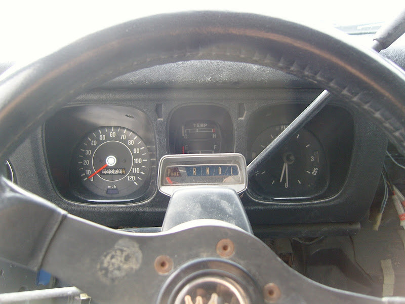
That is the plan. Way less realestate on the dash, all the information I need. Looking at the stock dash it will go between the speedometer and tachometer. The cutout for the stock fuel gauge and water temp will be opened up, mostly in a downwards direction. I don't think it will mess up too much of the stock looks of the dash. The tablet I want to run in the center of the dash will do that...
Re: Jacob's goon build
Posted: Tue Jan 03, 2017 10:36 pm
by Laecaon
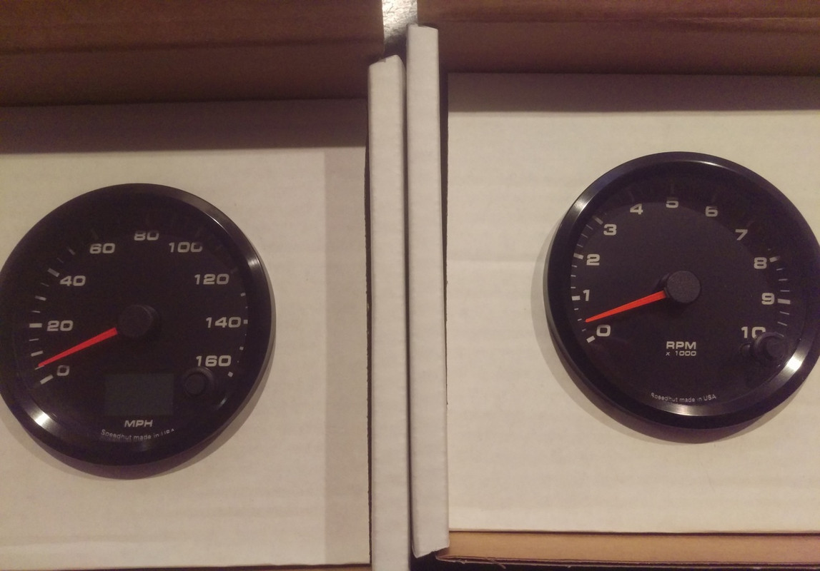
Ooo purdy.

Re: Jacob's goon build
Posted: Wed Jan 04, 2017 10:06 am
by wayno
So this is the second time you have changed the gauges, you didn't like the white ones?
Re: Jacob's goon build
Posted: Wed Jan 04, 2017 1:19 pm
by Laecaon
Um, whites one were stock. And then I got a 510 tach I never used. Wasn't going to make that white. Also I didn't feel like keeping the speedometer cable driven. And the stock tach doesn't go as high as my engine can go.
Re: Jacob's goon build
Posted: Wed Jan 04, 2017 3:24 pm
by wayno
So what gauges were these on the first page of this thread that are dated 2011?

Re: Jacob's goon build
Posted: Wed Jan 04, 2017 5:30 pm
by Laecaon
Stock 510, with the 510 clock on the right. I then painted those white. I then acquired a 510 tach. But that is too rare of a part to mess up painting it white.
I really only painted them white so I could see them better. The lights reflected off the white way better than the black. But now with new well lit gauges, back to black.
Re: Jacob's goon build
Posted: Wed Jan 04, 2017 5:40 pm
by wayno
OK, I didn't know you painted what you had, I just skimmed thru your thread looking at photos and came to the conclusion that you were going on to your 3rd set of gauges now, I didn't read the text.
The reason I skimmed was because I wanted to see how much room you were going to have for your screen in the middle, and I thought the white gauges looked good.
Re: Jacob's goon build
Posted: Wed Jan 04, 2017 6:26 pm
by Laecaon
The screen wont be any wider than the stock opening. But I will have to open it up height wise.
Re: Jacob's goon build
Posted: Mon Feb 06, 2017 1:24 am
by Laecaon
Update because I have some pictures.
First up, I acquired a FC RX7 oil cooler. It is about the max size I can fit behind the grill. But more importantly these oil coolers come with a thermostat/bypass valve built in so you dont over cool. Its not fit quite yet, and I need to readjust the front end bracing to make it fit, but you get the idea of where it is going.

After my sudo failure at making my own bushings (succeeded at making 2, needed 8) I looked elsewhere. These are energy suspension universal bushings for various things, 70A durometer. At least they actually isolate the hardware from the chassis, and they were too badly priced either $30.


So then to make these work I needed to actually get some numbers. First I needed to remove the stock crossmember. This meant supporting the engine from above, so to make sure things didnt move much I took a few measurements. Then I swapped to my new crossmember (which bolted in nicely!). Whoa, I have like 5 inches of space between the crossmember and engine brackets (5 3/16th to be exact). So then I needed to figure out the standoffs for the engine mounts. I knew two things, I needed a 1/4" plate for the bushing to go through, and the total tower height needed to be 3.55". Off to solidworks! And I whipped something like this up:

Print out and cut some paper templates:

Lay down the template and mark your material, I used a fat red sharpie (really should buy some lay out fluid). Magnets are way nicer than using your fingers:

Drill out the corners, 1/2" drill for a 1/4" radius:

Rough cut the inside holes:

Cut out the parts, finish as necessary (damn I love my belt sander, makes for nice straight sides) (yes I need to polish the inside a bit more):

And "assembled" with magnets. Just need to finish all the parts, then I can get it mounted to the car!

Re: Jacob's goon build
Posted: Mon Feb 06, 2017 1:25 am
by Laecaon
Oh, and my phone is taking shitty pictures. The glass over the camera is cracked, and there is dust in there...
Re: Jacob's goon build
Posted: Tue Feb 07, 2017 10:47 pm
by Laecaon
First up, I bought one of these:

It has a couple of design flaws, but I can fix that. But mostly it takes an odd 1/2" by 18" belt.
So I bought a 3"x18" belt.

Clamped a razor blade on a 1/2" spacer...

And cut the belt to size!

And here is a mostly finished engine bracket! I may want to lift the engine another 1/2"...

And since the motor is moving back, I need to re-do my tranny mount. Got the angles all figure out, and figure out a design that provides maximum clearance. And then I realized its a bit like TechnoToyTunings... but mine gives more clearance, and uses a S13 tranny mount, and is designed to move the tranny back in the car.

Re: Jacob's goon build
Posted: Wed Feb 08, 2017 2:53 pm
by draker
I like all the solidworks modeling!
Nice work on making those parts come to life.
Re: Jacob's goon build
Posted: Sun Feb 26, 2017 12:42 am
by Laecaon
Updates because Ive been doing stuffs. I actually pulled out my camera for pictures so at least things are actually visible.
Picture of the Dog:

So I cut off the radiator outlet. Being directly above the intercooler outlet there was a clearance issue...

I made a piece at work to kick the outlet up at a 45 degree angle, helps to get the radiator hose away from the intercooler pipes. Gonna get it welded on today...

One steering knuckle just about ready to weld up! Man that was a lot of grinding...

Just need to notch the seams for a deeper penetration weld. Gonna have them TIG welded.

Here you can see how I did it. All 3 pieces have 2 1/4" holes drill in them for a precision alignment, and then 2 1/4" pins orientating them all.

This picture was difficult to take, but its to show that I dropped the balljoint/tierod mount down 1.5"

Something like this is my desired ride height. Plenty of travel room (though right now the tire is too far outboard)

I wanted to take a head on shot, but its cold and I didnt feel like opening the garage door. You cant really tell, but from head on you can see the balljoint is about 1/4" above the LCA pivot. Which this is the reason for dropping ball joint on the knuckle. I should have a better roll center than I did before with ZX struts and 1" RCAs.

Oh yea, I did make my Tranny mount. I totally forgot to take during pics. But it went together nicely. Its a stout piece. This shot is to give a general feeling of the space under the car.

Close up of the mount. Keeping the S13 rubber mount, makes it easy, use as many S13 parts as I can!

Moving the engine back does lead to a few clearance problems. Decided to move the fuel pressure regulator to the firewall. And I need to sort the heater inlet, the hose is rubbing the back of the head.

Re: Jacob's goon build
Posted: Sun Feb 26, 2017 7:44 am
by DRIVEN
So...Canby?
Re: Jacob's goon build
Posted: Sun Feb 26, 2017 6:47 pm
by draker
Dude! nice work on that tranny mount!
Re: Jacob's goon build
Posted: Mon Feb 27, 2017 11:16 am
by Indy510
Wow those control arms must be raised 1.5" or more from stock? ... are you going to raise the front of the T/C rod? Some 510's have the adjustable T/C rod pivot welded to the frame rail, when the control arms are raised one inch:

Re: Jacob's goon build
Posted: Tue Feb 28, 2017 8:43 am
by Laecaon
I really don't think so. I'm avoiding heim joints at all costs. They are raised 2 inches. But being outboard a tad more helps with the upward clearance.
Probably leaving the TC rods mostly the same, but adjustable and a clevis at the LCA. Sway bar is my lowest priority. But it will make it on.
Re: Jacob's goon build
Posted: Sun Mar 05, 2017 10:52 pm
by Laecaon
Quick comparison of a stock knuckle and my modified one.

Both knuckles finally done. Had Draynor tig them, but for some reason some of the welds were contaminated so I ground out the weld, heated them up to 150 degrees and layed down some mig beads. Had some wire feed problems (you can see on the right). But I am happy with them.

And mounted!


Bottom of crossmember to LCA pivot: (roughly 3.25")

Bottom of crossmember to balljoint: (roughly 3")

So, raising the LCA pivot up 2 inches, and dropping the balljoint on a S13 knuckle 1.5" results in an almost level LCA and a ride height I like. Not optimum, but basically what I had with my ZX struts. And now I have all the options in the world for brakes and suspension setups.
In other news, my Radiator is dead. The 45 piece was successfully welded on. But in the process one of the cooling fins was blown open. I think I have found a non ebay radiator that will work. Just need to call them up for final dimensions.
Re: Jacob's goon build
Posted: Mon Mar 13, 2017 9:15 pm
by Laecaon
More suspension fun! Got the TC rods made. Well mostly. Erm, they are a tad long at the moment, easy enough to trim them down. Also I dont have quite enough thread engagement at the TC pocket. Well anyways onto the pics!
Here is one of the assemblies (lacking lock nuts):

Ordered some special Airplane bolts. I havent seen a higher rated bolt for stress. And I am interested in shear strength. And I got the idea from Futofab...

At the TC pocket. Barely visible is a aluminum washer designed to center the TC rod, and to attach the boot that will cover that early 80s Toyota Corolla inner tie rod.

And a general ish shot looking at the LCA a bit. Clevis joint works well.

And another shot. I think it looks really good. Save for that green nut... That middle piece I made out of 303 stainless. Adapts from M14x1.5 to 5/8-18 LH.

Re: Jacob's goon build
Posted: Mon Mar 13, 2017 9:26 pm
by Laecaon
Also I have been giving it some thought, and now need to do some research. Due to how I raised my LCA pivot, I may want to raise the TC rod after all. If you imagine a triangle of the LCA pivot/TC rod pivot/ and balljoint, the wheel actually swings in a arc from the imaginary line from the LCA pivot to TC pivot. Anyways, I need to see what that means.

