How to - Rebuild/Repair electronic e12-80/92 distributor
Posted: Sat Oct 04, 2014 2:59 pm
How to - Rebuild a 1979-1983 e12-80 , e12-92 , e12-93 .. electronic distributor (matchbox)
------------------------------------------------------------------------------------------------------------------
This is a general guide "how to" on rebuilding a e12-80/92/93 electronic pickup distributor (aka "matchbox").
The reason this is said to be a "general" guide is that the distributor used for example below came originally off a 1979 280zx 5spd coupe N/A car.
It is a 6-cylinder (L28e) , and the 4-cylinders are generally the same in concept , but could be slightly to somewhat different during the process.
My bet is they are fairly close , but for the sake of safety
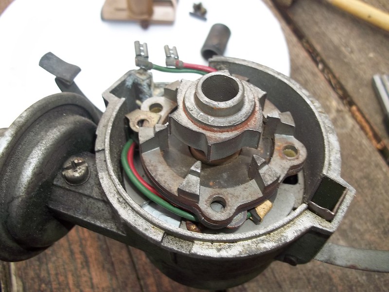
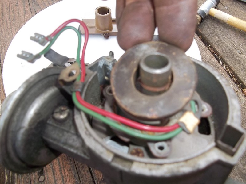
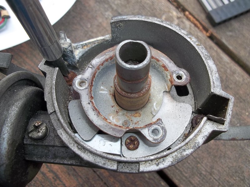
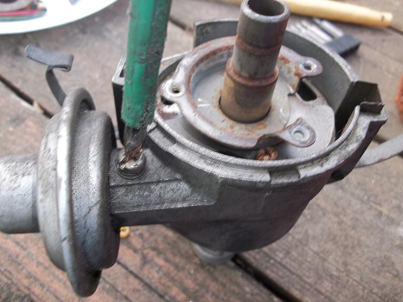
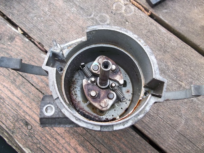
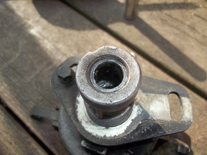
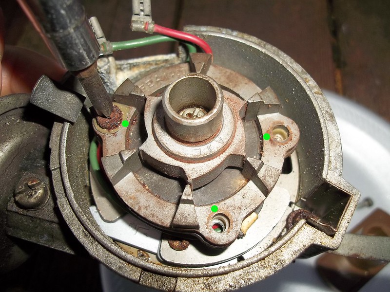
(STEP 1:) ---- Start with a distributor. Currently the one pictured has the ignition module (thing bolted onto the side with (2) flat or phillips head screws , and 2-wires coming out of it) removed. The distributor cap , and rotor are also removed. NOTE: when taking off the ignition module there can be some corrosion that holds the screws in. My method is to make sure there is a GOOD firm grip ... tighten them just a TOUCH ... then loosen them all together. This method is much the same for breaking the corrosion seal on brake-line nuts. Be very careful , and take your time. Sometimes they will just come right out , and sometimes not. This applys to all hardware on this distributor. The (2) green dots in the picture below represent where the ignition module bolts to.
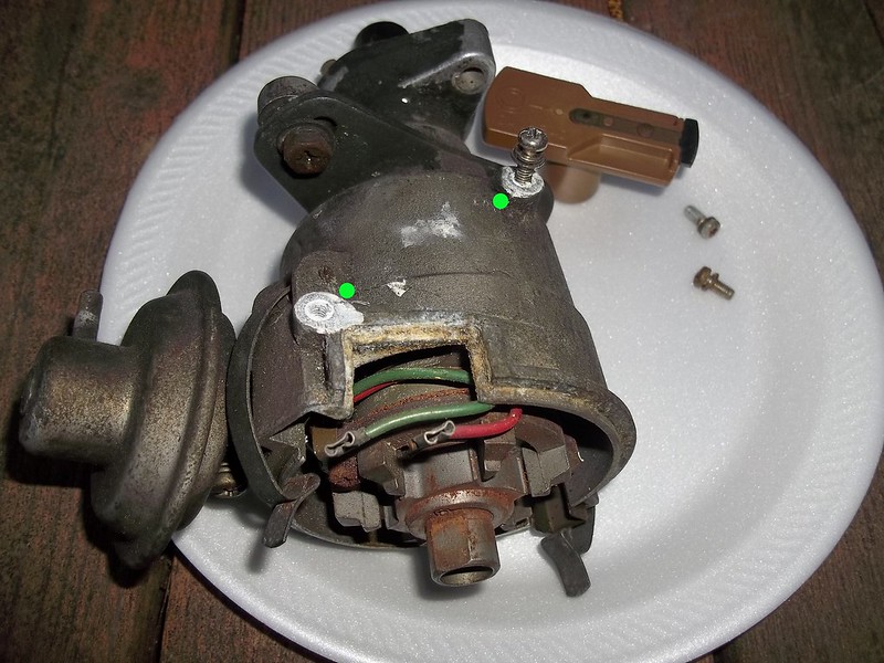 001 by 71240z, on Flickr
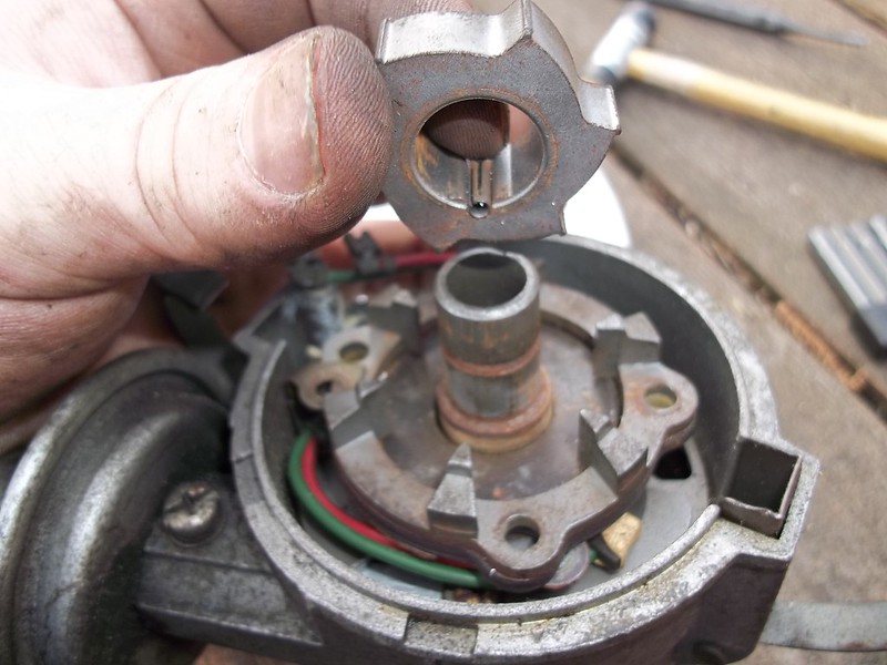
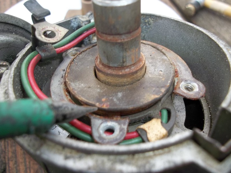
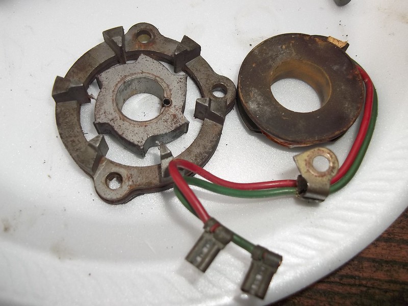
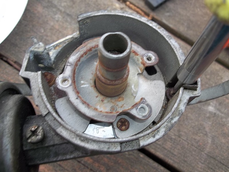
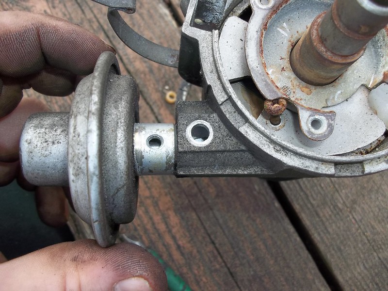
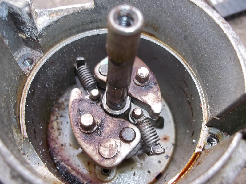
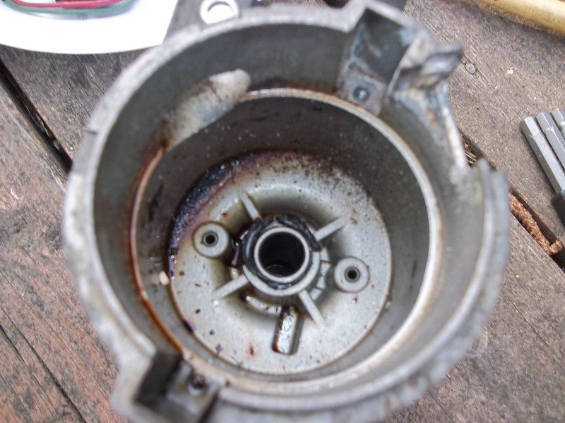
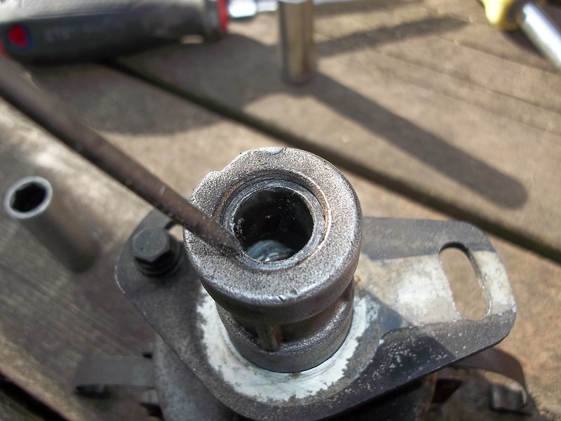
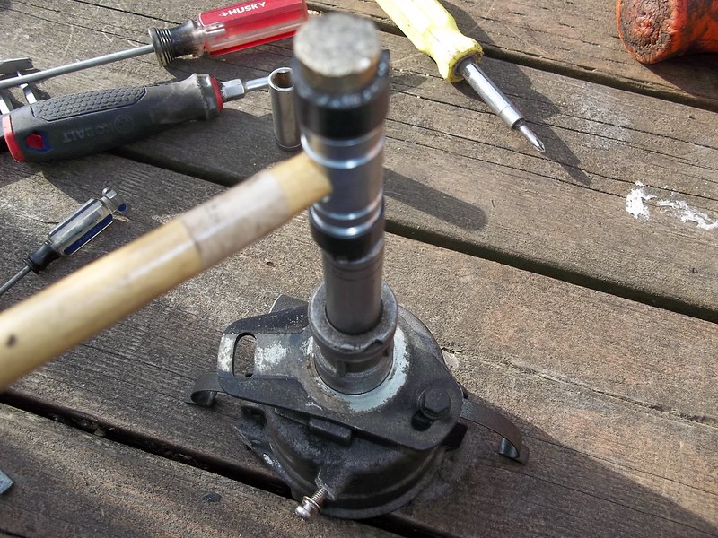
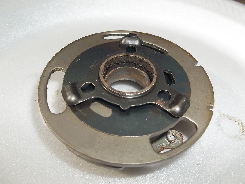
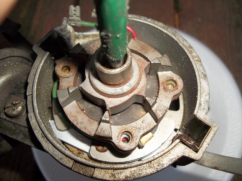
(STEP 2:) ---- Next we're going to tip the distributor vertically (upward towards the sky) , and remove (3) screws that hold in the "stator" assembly. Be very careful... around the stator. The stators screws are bolted to the "breaker plate" assembly.
 002 by 71240z, on Flickr
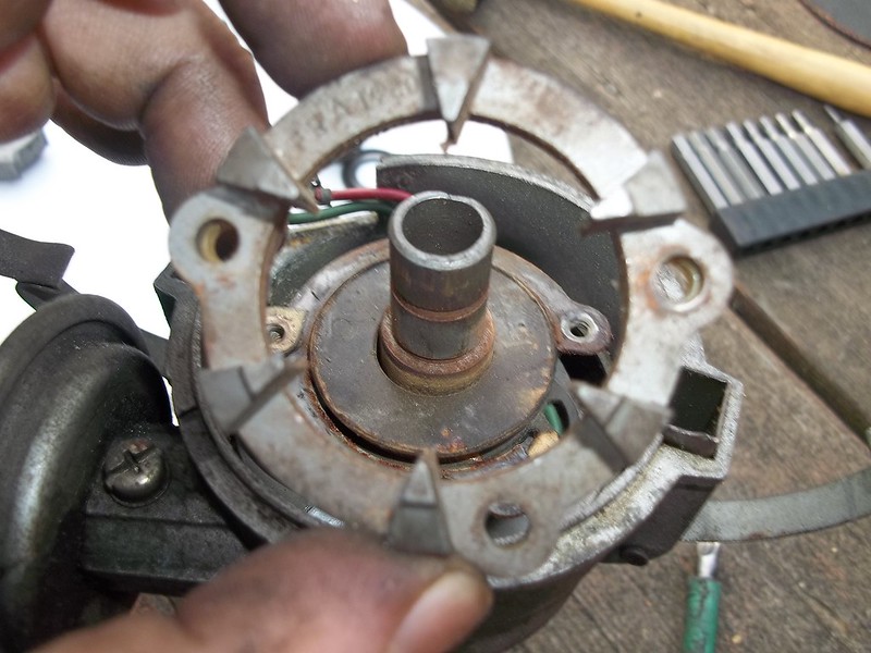
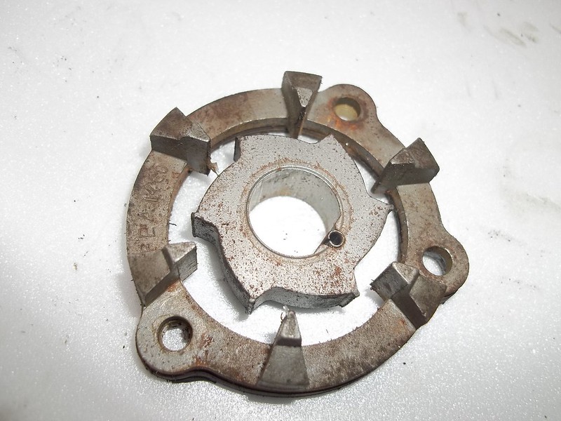
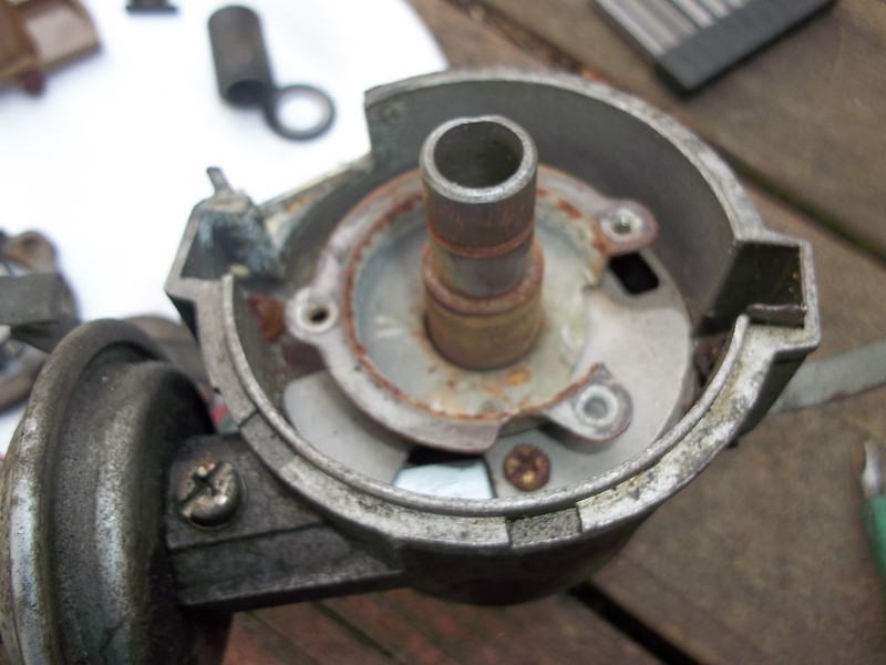
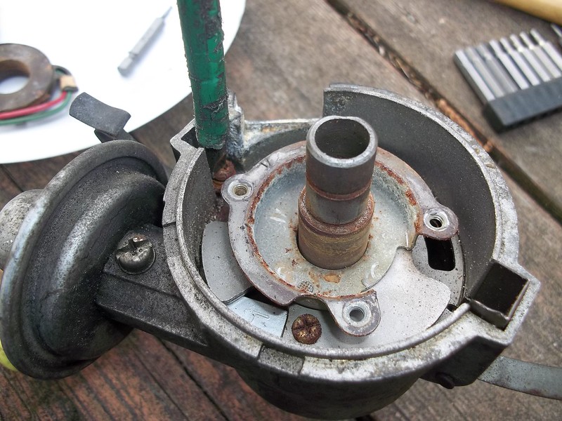
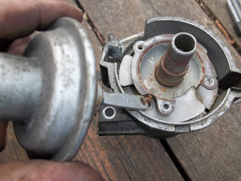
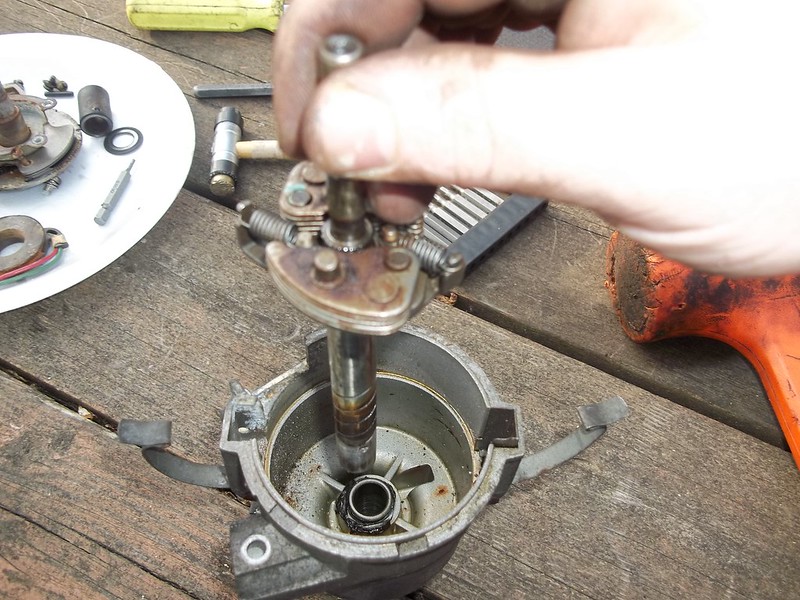
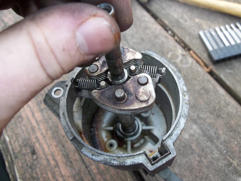
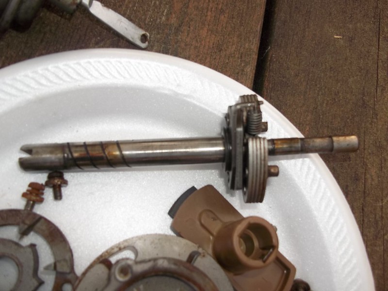
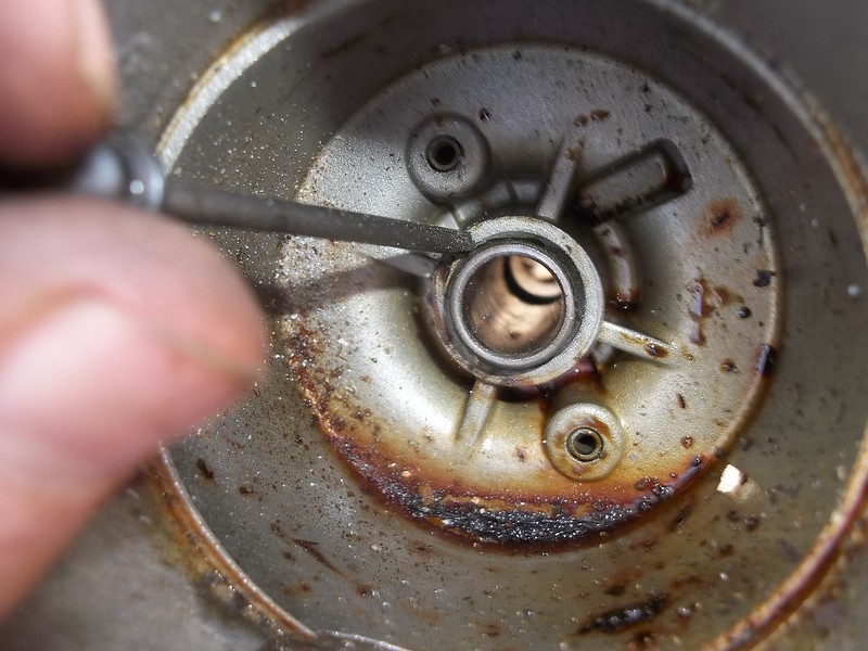
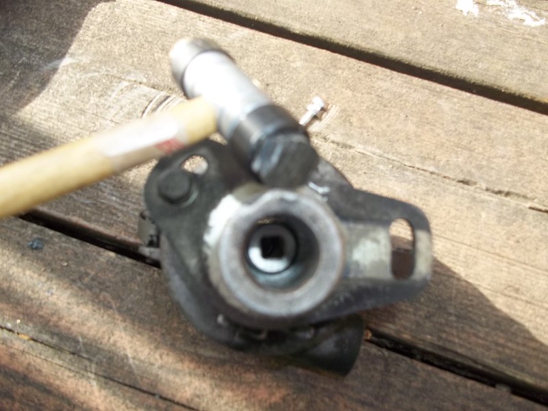
(STEP 3:) ---- Remove the center screw from the shaft.
 003 by 71240z, on Flickr
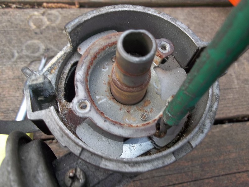
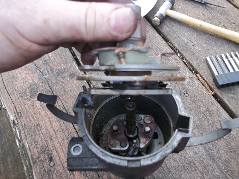
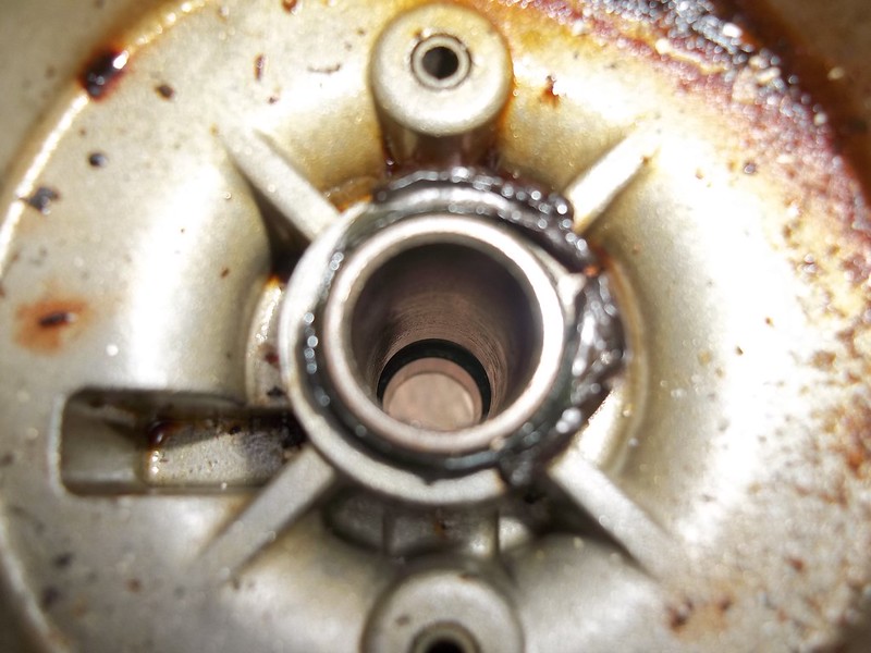
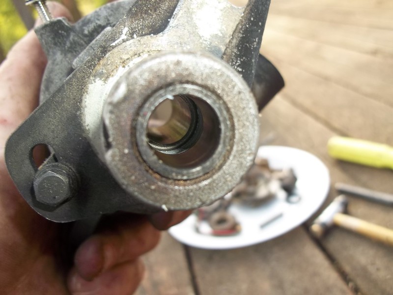
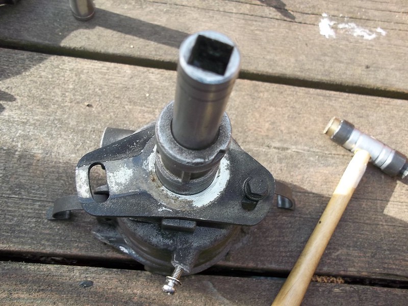
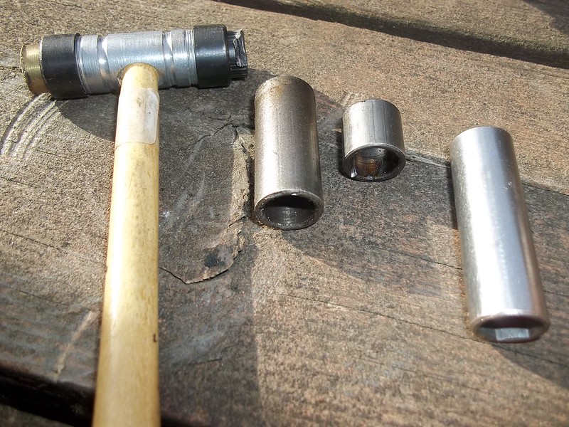
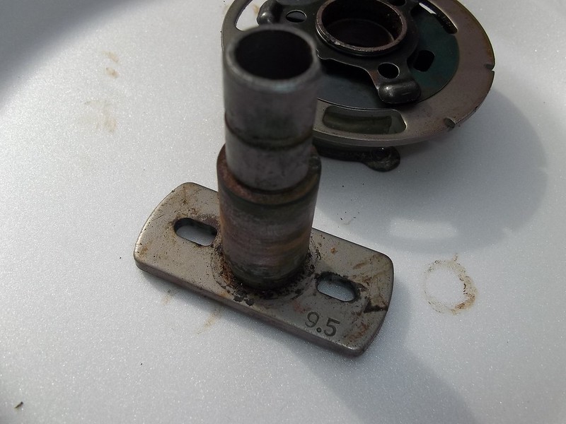
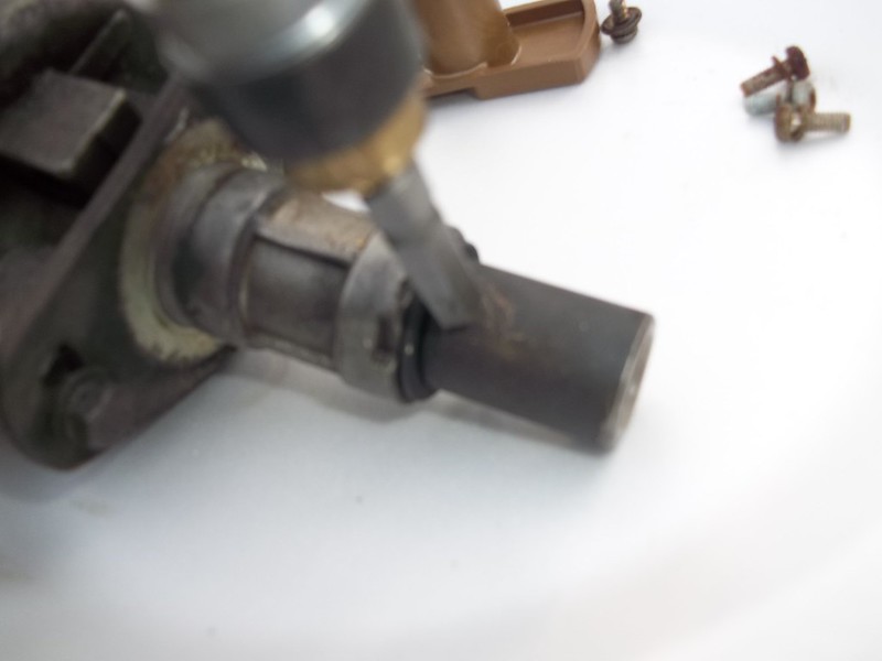
(STEP 4:) ---- Next turn the distributor on it's side. Look at the bottom tail portion. The hole shown in this picture has a roll-pin inserted into it. We're going to carefully punch it out with a correct sized pin punch. Make sure the "neck" (straight portioned part of the tool) is long... enough to do the job, There are a lot of short punchs out there these days. Remove the spacer , washer , and roll-pin once completed.
 005 by 71240z, on Flickr
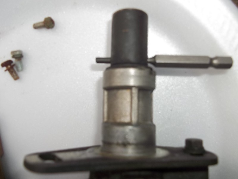
Small brass/nylon hammer shown against a pin-punch.
 006 by 71240z, on Flickr
 007 by 71240z, on Flickr
(STEP 5:) ---- Remove the roll-pin , spacer , and washer. Set aside in a bin or collector for all the small parts.
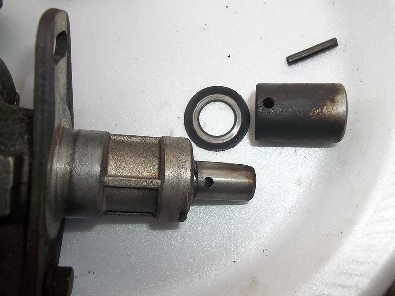 008 by 71240z, on Flickr[/quote]
------------------------------------------------------------------------------------------------------------------
This is a general guide "how to" on rebuilding a e12-80/92/93 electronic pickup distributor (aka "matchbox").
The reason this is said to be a "general" guide is that the distributor used for example below came originally off a 1979 280zx 5spd coupe N/A car.
It is a 6-cylinder (L28e) , and the 4-cylinders are generally the same in concept , but could be slightly to somewhat different during the process.
My bet is they are fairly close , but for the sake of safety
(STEP 1:) ---- Start with a distributor. Currently the one pictured has the ignition module (thing bolted onto the side with (2) flat or phillips head screws , and 2-wires coming out of it) removed. The distributor cap , and rotor are also removed. NOTE: when taking off the ignition module there can be some corrosion that holds the screws in. My method is to make sure there is a GOOD firm grip ... tighten them just a TOUCH ... then loosen them all together. This method is much the same for breaking the corrosion seal on brake-line nuts. Be very careful , and take your time. Sometimes they will just come right out , and sometimes not. This applys to all hardware on this distributor. The (2) green dots in the picture below represent where the ignition module bolts to.
001 by 71240z, on Flickr(STEP 2:) ---- Next we're going to tip the distributor vertically (upward towards the sky) , and remove (3) screws that hold in the "stator" assembly. Be very careful... around the stator. The stators screws are bolted to the "breaker plate" assembly.
002 by 71240z, on Flickr(STEP 3:) ---- Remove the center screw from the shaft.
003 by 71240z, on Flickr(STEP 4:) ---- Next turn the distributor on it's side. Look at the bottom tail portion. The hole shown in this picture has a roll-pin inserted into it. We're going to carefully punch it out with a correct sized pin punch. Make sure the "neck" (straight portioned part of the tool) is long... enough to do the job, There are a lot of short punchs out there these days. Remove the spacer , washer , and roll-pin once completed.
005 by 71240z, on FlickrSmall brass/nylon hammer shown against a pin-punch.
006 by 71240z, on Flickr007 by 71240z, on Flickr(STEP 5:) ---- Remove the roll-pin , spacer , and washer. Set aside in a bin or collector for all the small parts.
008 by 71240z, on Flickr[/quote]