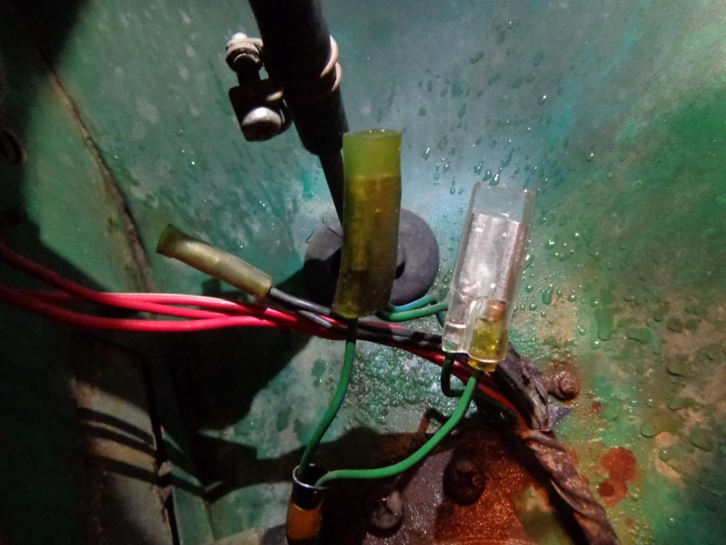
Side Marker Light Conversion
Posted: Sun Nov 10, 2013 9:51 pm
This works for any of the side marker lights with metal housings. The ones I'm working with here are from my 510, but I will post a pic below of the 620 unit to show how similar it is.
My quest started by reading this article in DQ Vol. 1 Issue 1:
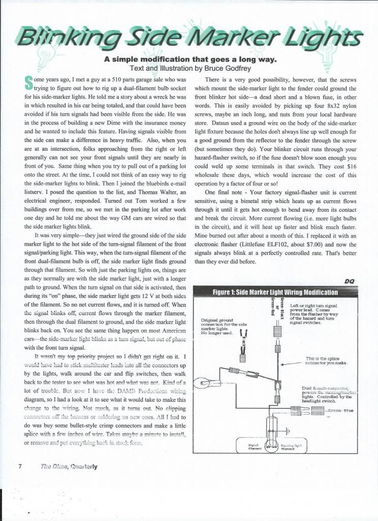
After reading this and looking at my side marker lights, it occurred to me that the factory ground wire is attached directly to the marker housing. So even if you use a nylon screw like the author suggests, you will still have the entire backside of the housing un-protected from grounding out on the body or anything that comes into contact with it. I have found in my collection of parts a side marker unit that has a full rubber sleeve protecting the entire housing. I'm guessing this is from a later 280 Z car or something. I suppose if you have this rubber sleeve, and you drill out the holes the mounting screws go through, you will be ok.... But that's not safe enough for me.
So I set out on a mission today. I was in search of a light bulb socket to replace the factory single filament bulb with something else. I had envisioned using a mini spade bulb with a plastic twist-on socket like this one I used on my 620 conversion:
http://community.ratsun.net/topic/57342 ... 620/page-4
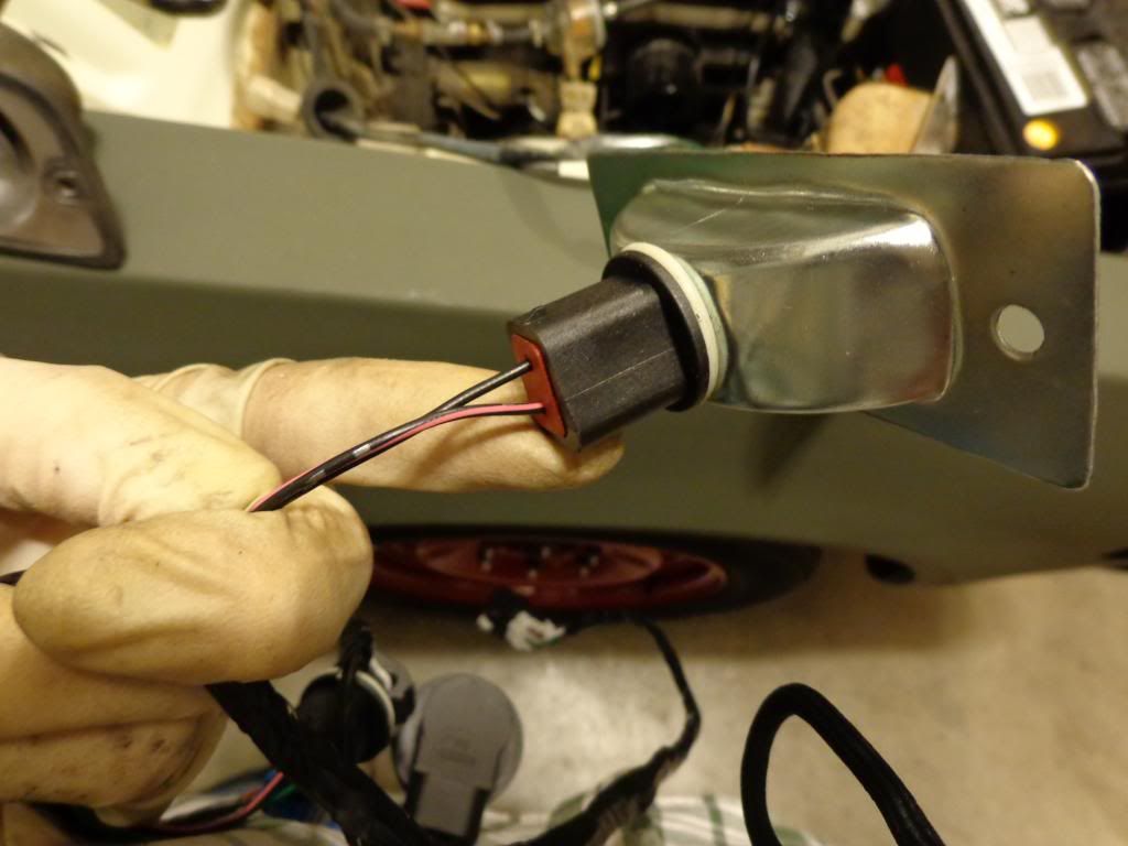
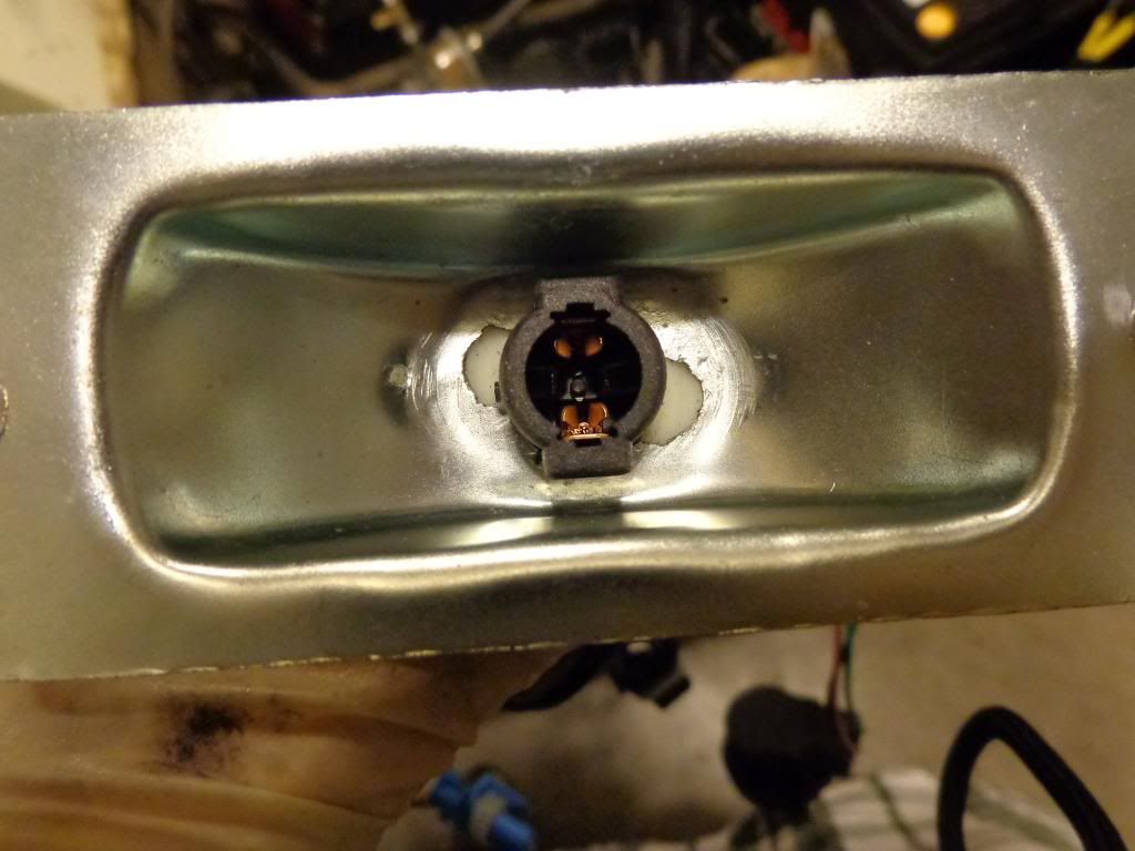
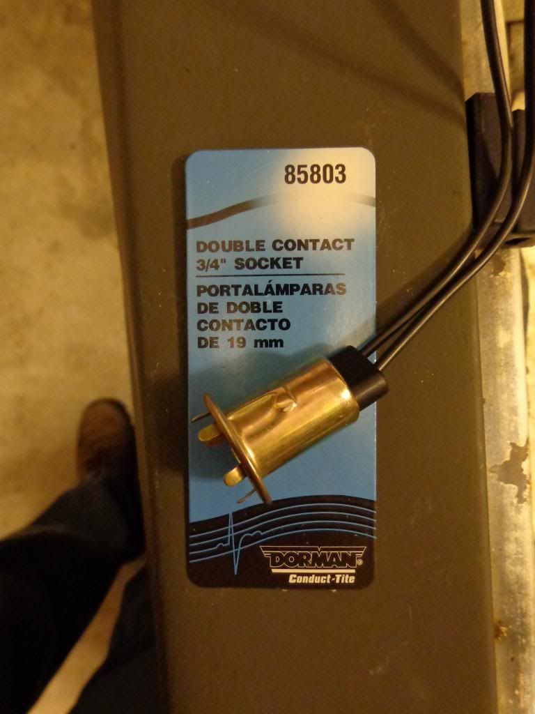
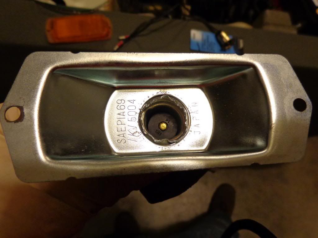
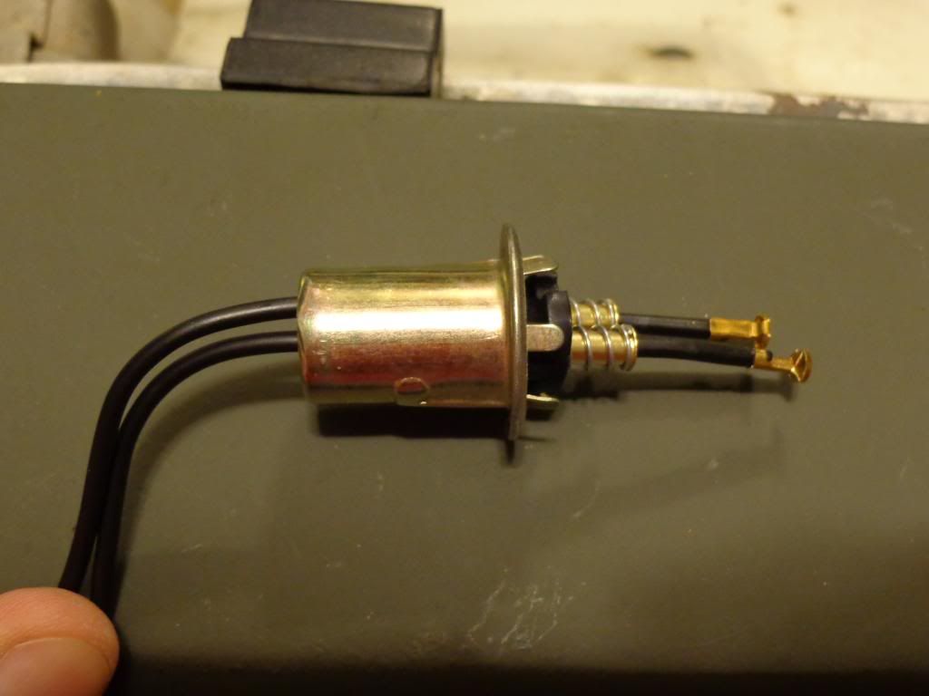
Unfortunately that socket and all the ones I found at the parts store were too small. But, I did find this one; its a dual filament 1157 socket. The sockets cost $3.66 each, up here:
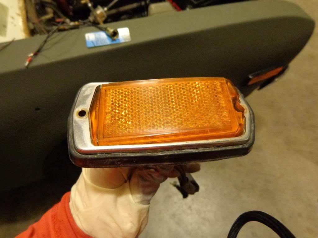
Here are the couple of side markers I'm using:
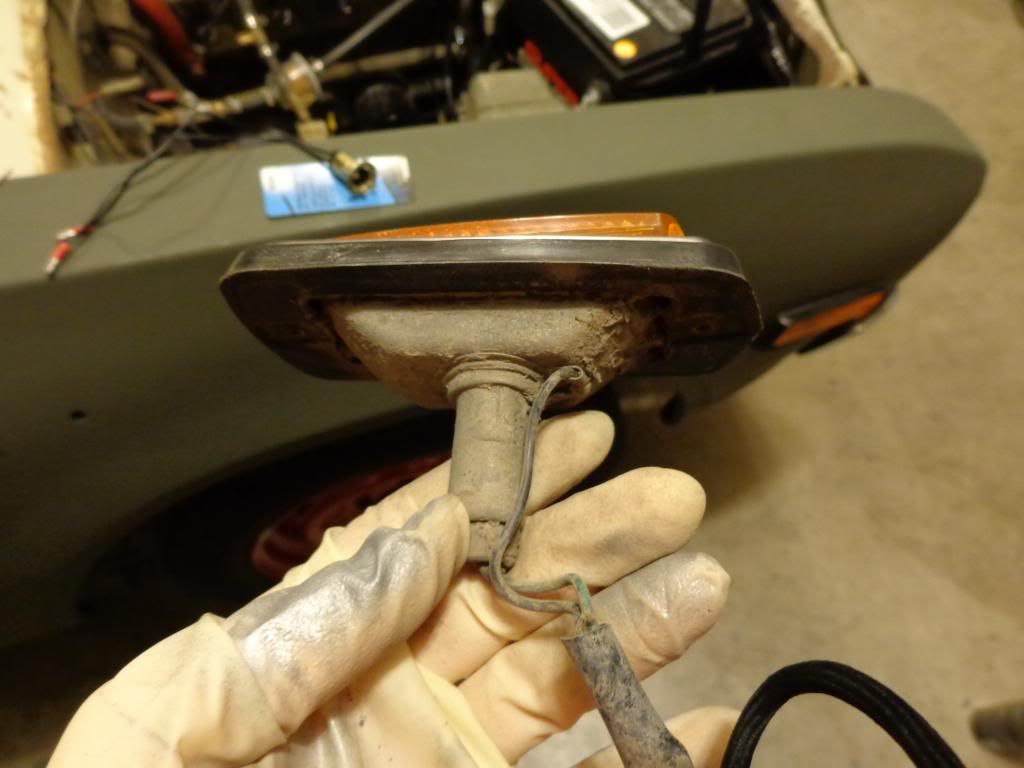
Here is that rubber sleeve I referred to earlier:
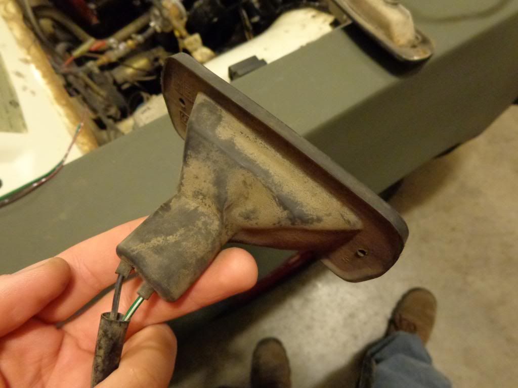
That rubber sleeve kept this housing in excellent shape over the years:
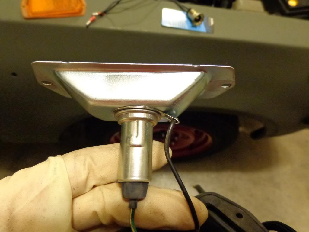
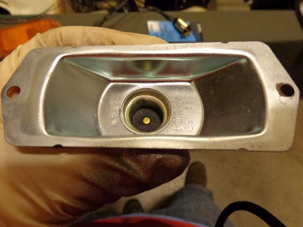
Here is one of the new Thailand units for comparison:
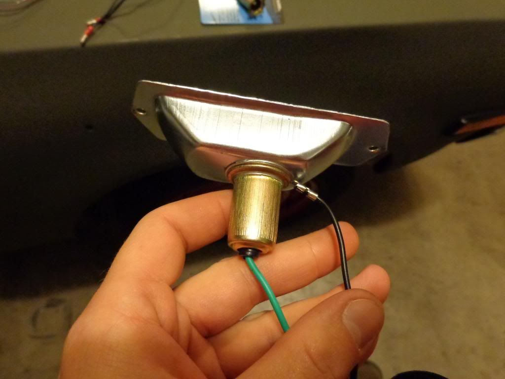
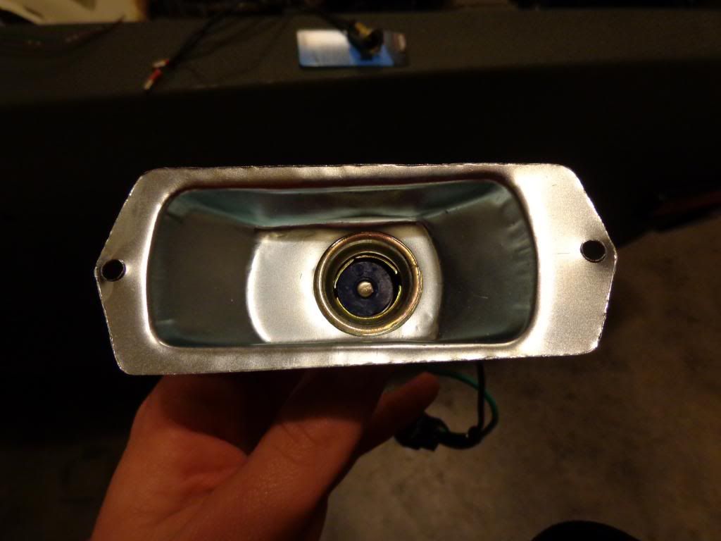
And the 620 unit for comparison:
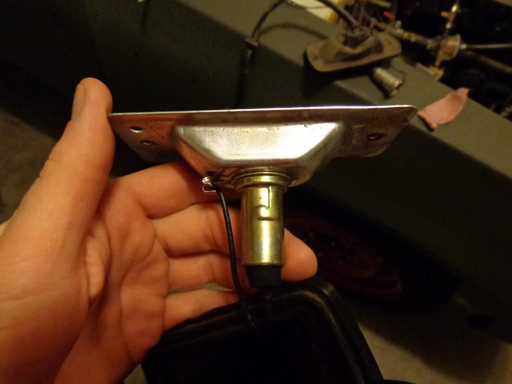
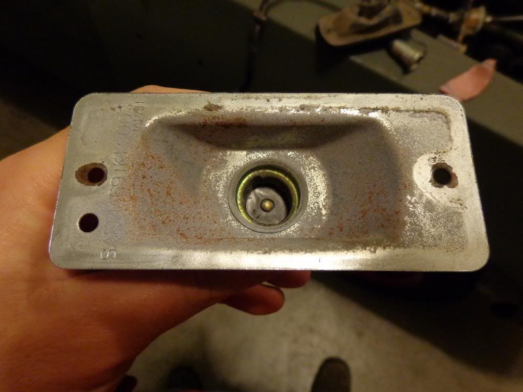
To remove the socket, I used one of my favorite tools:
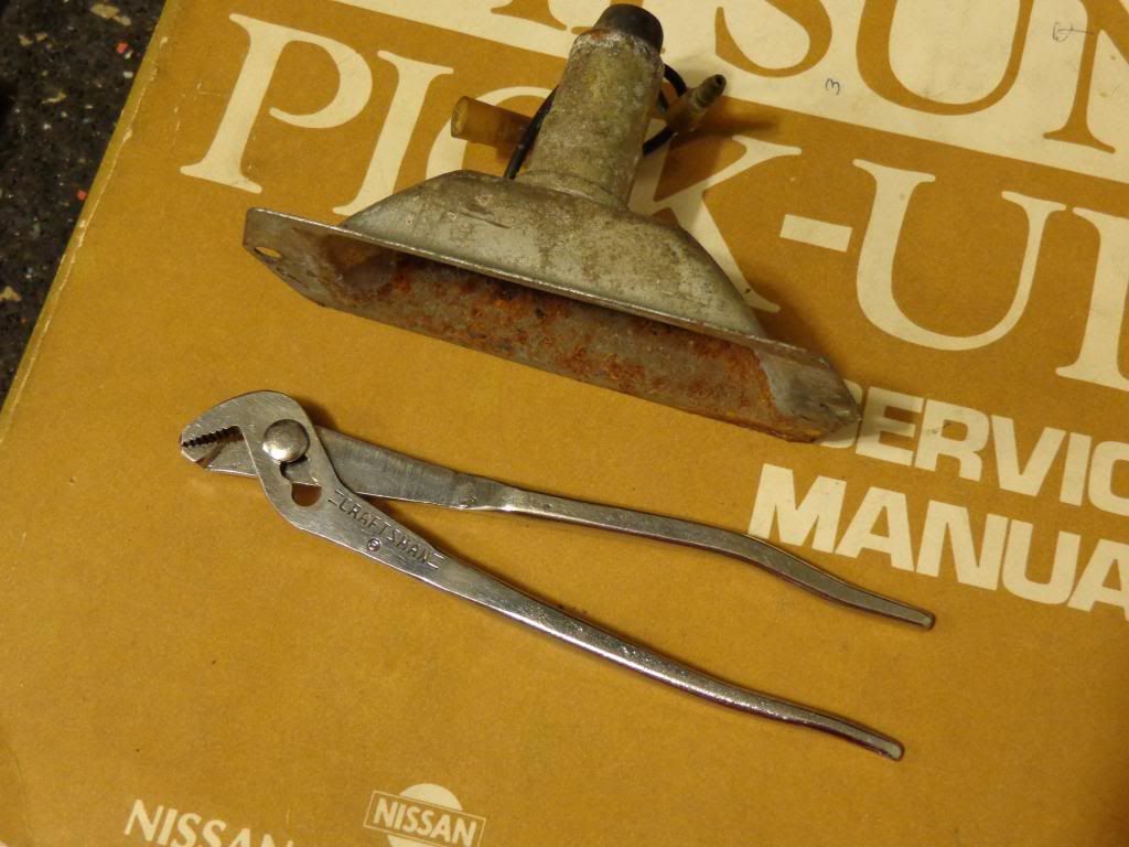
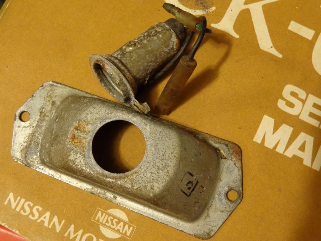
I just bent back the stamped edge and pulled the old socket off:
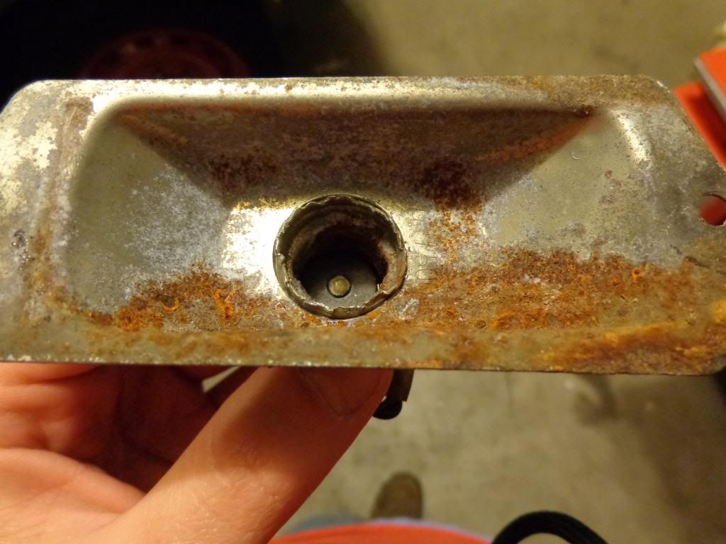
Afterwards, you're left with this:
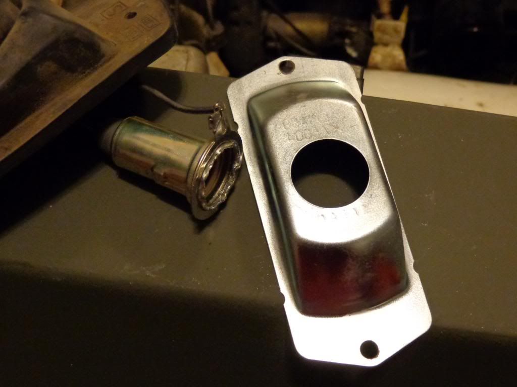
Next I put the new socket up to the housing. It's a little small, but it will work just fine:
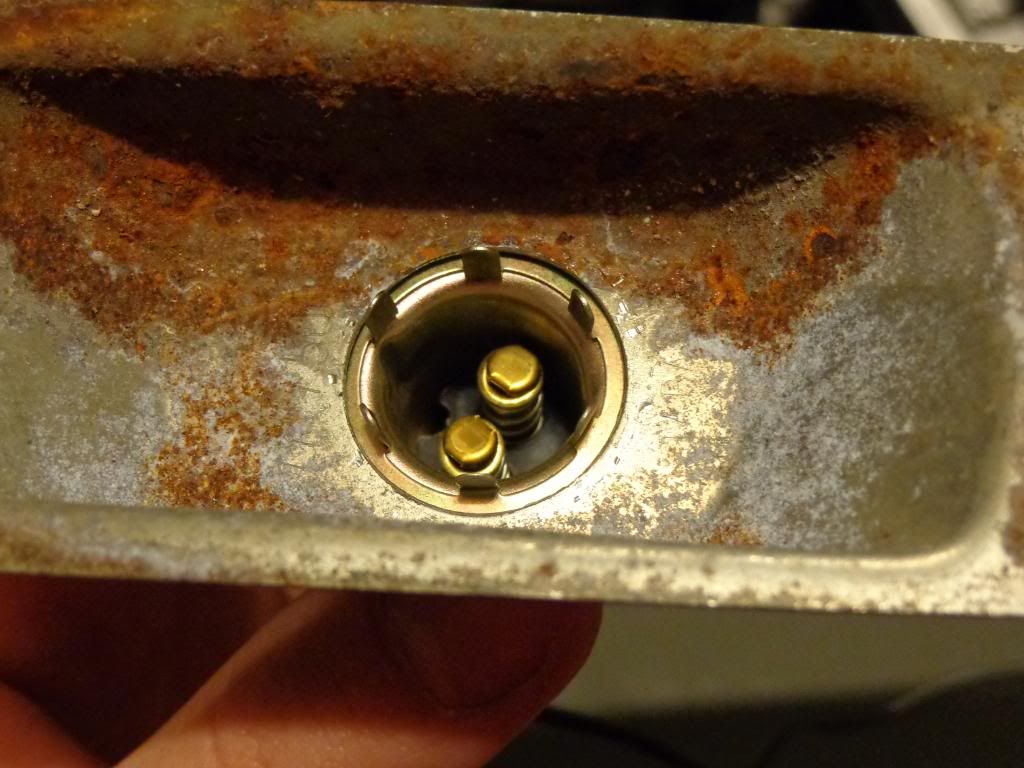
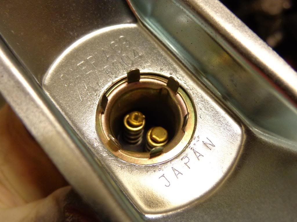
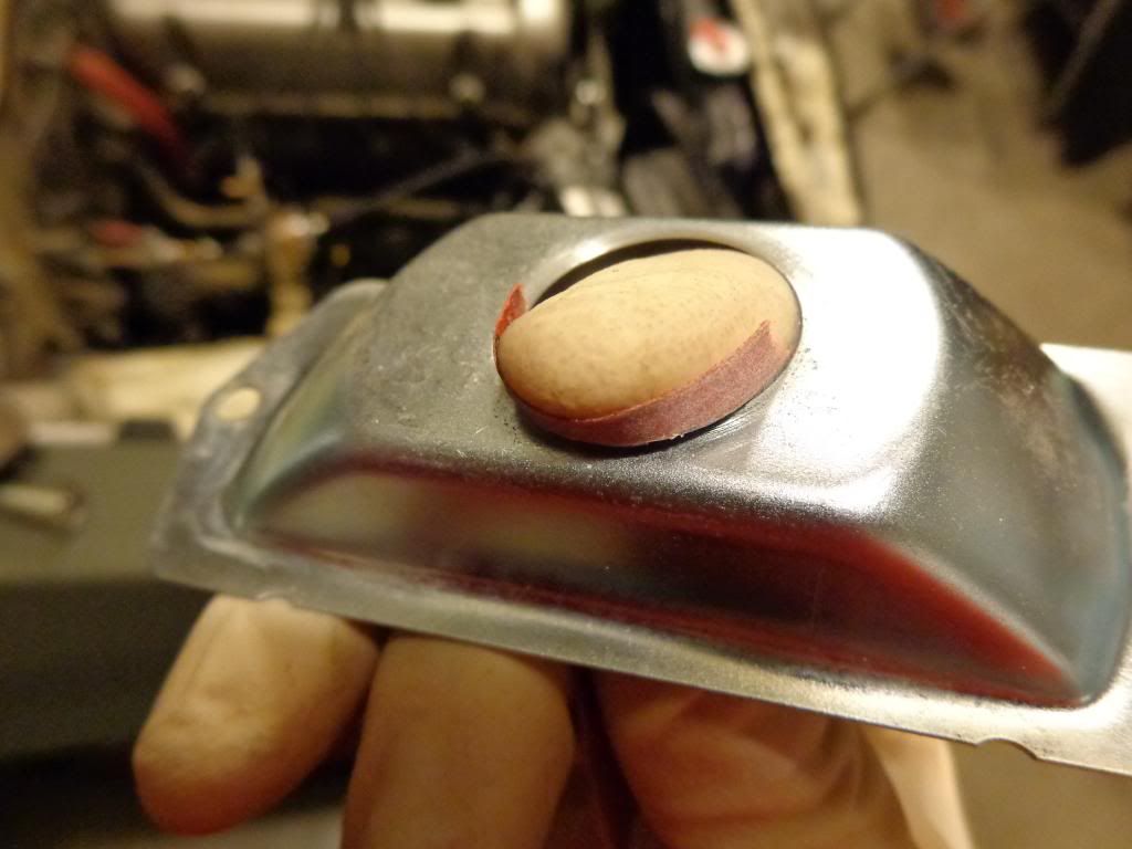
I'm going to solder these two pieces together to ensure a lasting bond and to seal out any moisture. So before joining them, first I pulled the wires out of the socket. Then I sanded around the opening on the outside of the housing and the edge of the socket down with some 400 grit. Then I cleaned them with some fast dissipating electronics cleaner:
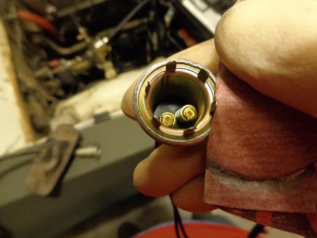
To get the tabs bent down easier during installation, I slightly bent all of them before installing it. The top tab, I bent more than the others, to help hold it in place:
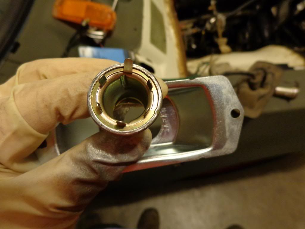
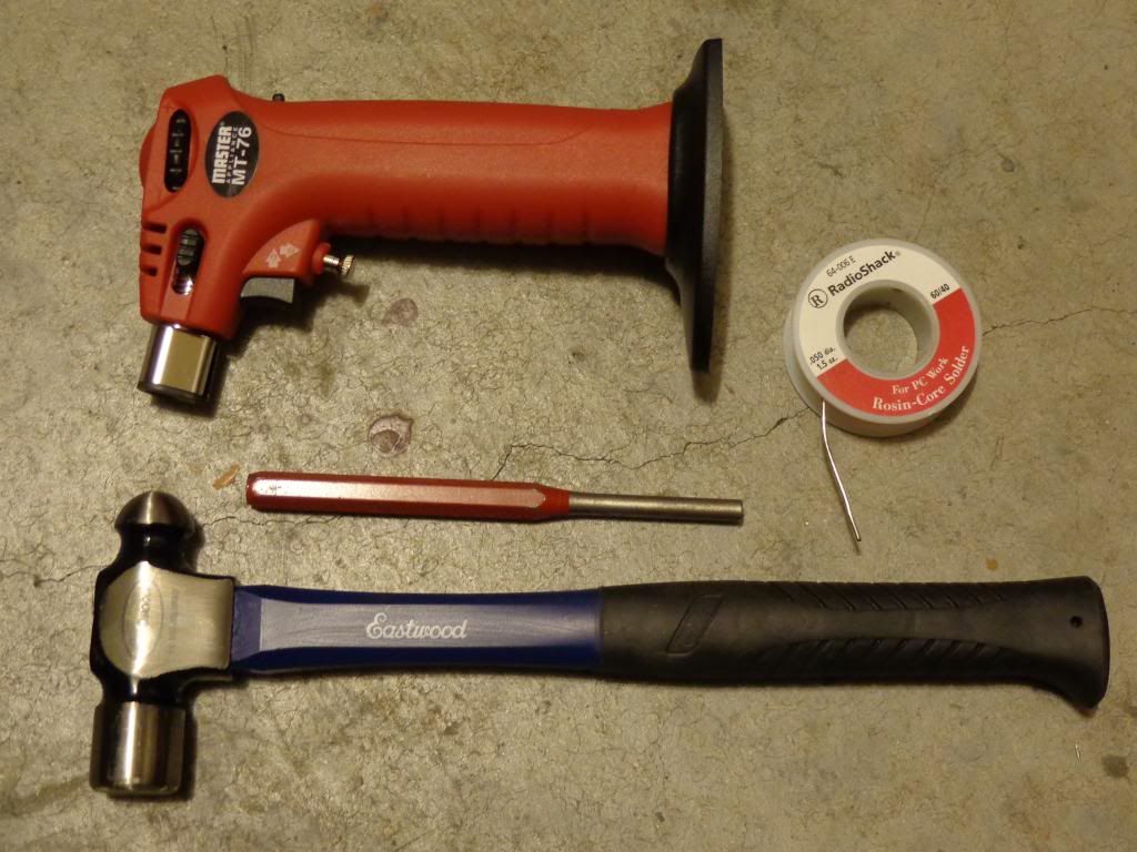
I used a vice to help hold the unit in place while I used a hammer and a punch to gently push the tabs over and in place. Then I soldered the joint. I used a mini-torch and some 40/60 rosin core solder. I soldered both sides:
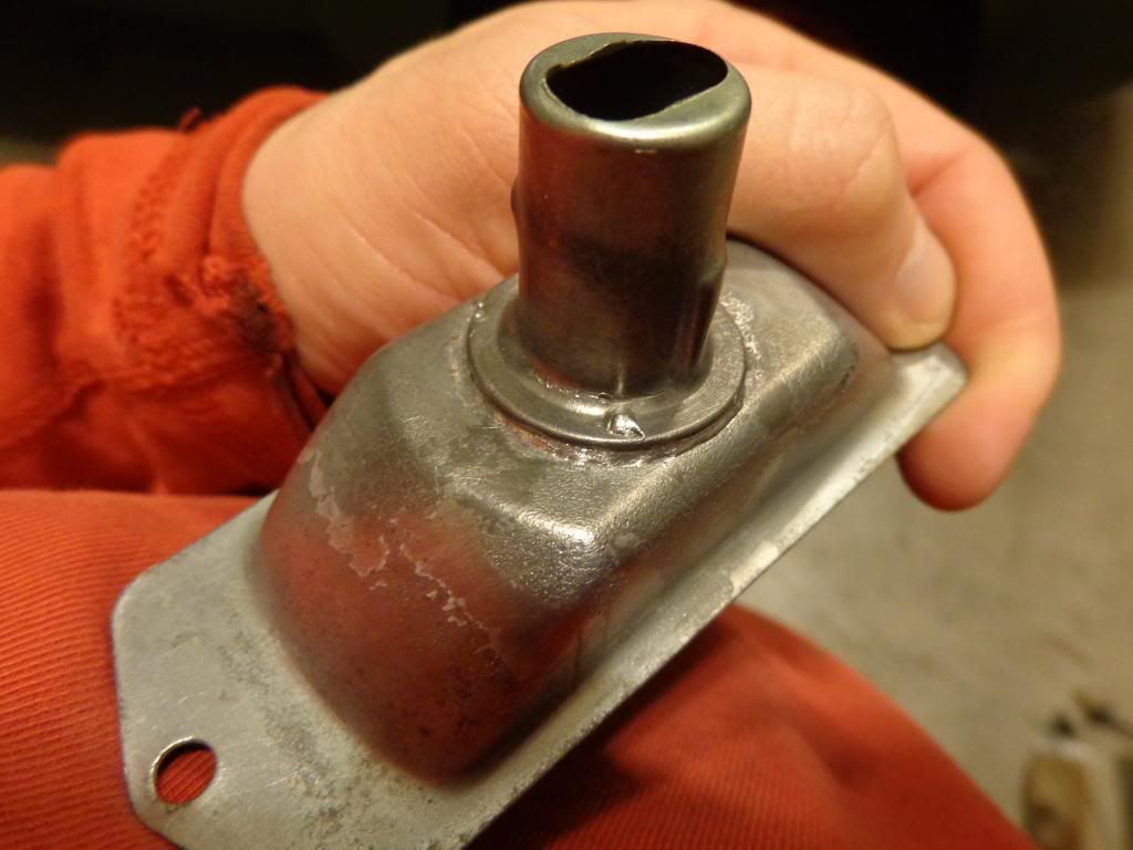
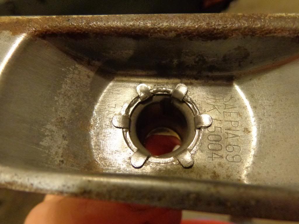
Next, I wire brushed the housing and painted it with some chrome spray paint:
(Don't forget to mask off, or stuff part of a paper towel down into the socket to keep the paint out of it)
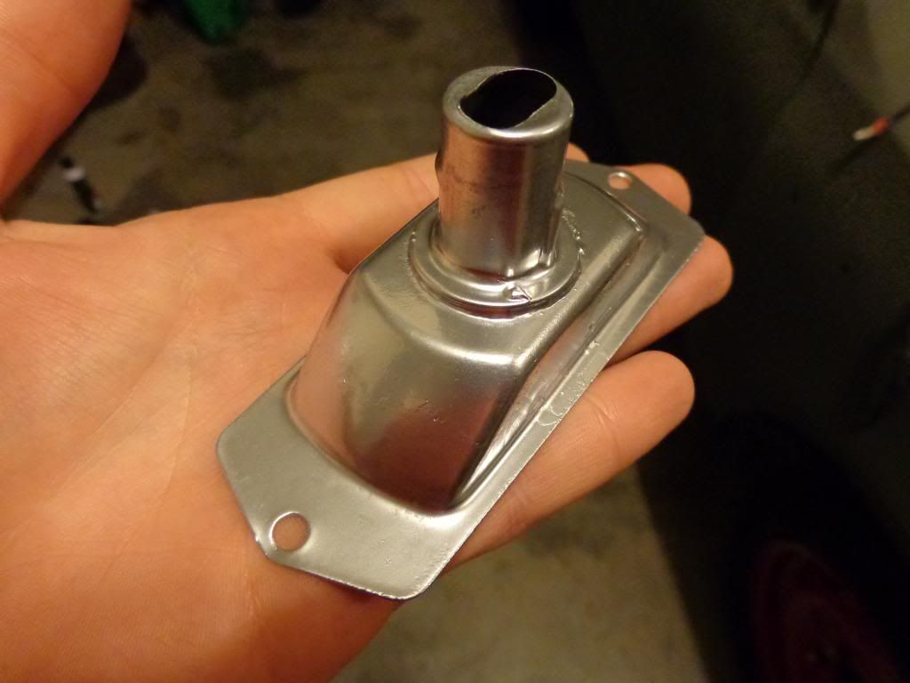
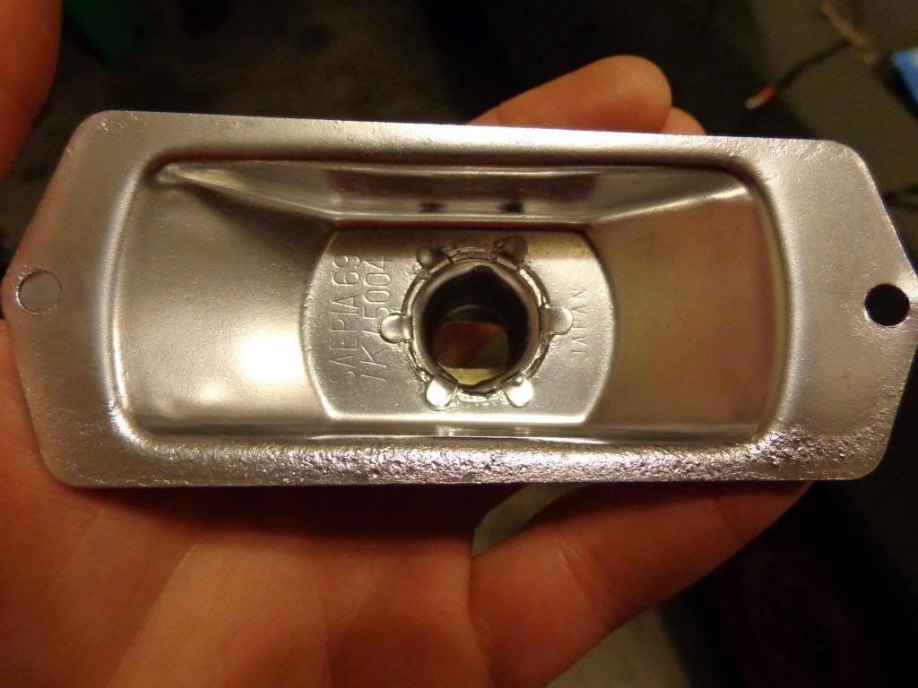
Now with that complete, I'm confident the conversion is safe.
I tested the circuit, and it works great. I am out of the connectors I want to use for the jumper wires, so once they arrive; I will solder them up and post pictures. I will basically be using the diagram given in the DQ article.
My quest started by reading this article in DQ Vol. 1 Issue 1:

After reading this and looking at my side marker lights, it occurred to me that the factory ground wire is attached directly to the marker housing. So even if you use a nylon screw like the author suggests, you will still have the entire backside of the housing un-protected from grounding out on the body or anything that comes into contact with it. I have found in my collection of parts a side marker unit that has a full rubber sleeve protecting the entire housing. I'm guessing this is from a later 280 Z car or something. I suppose if you have this rubber sleeve, and you drill out the holes the mounting screws go through, you will be ok.... But that's not safe enough for me.
So I set out on a mission today. I was in search of a light bulb socket to replace the factory single filament bulb with something else. I had envisioned using a mini spade bulb with a plastic twist-on socket like this one I used on my 620 conversion:
http://community.ratsun.net/topic/57342 ... 620/page-4


Unfortunately that socket and all the ones I found at the parts store were too small. But, I did find this one; its a dual filament 1157 socket. The sockets cost $3.66 each, up here:

Here are the couple of side markers I'm using:


Here is that rubber sleeve I referred to earlier:

That rubber sleeve kept this housing in excellent shape over the years:


Here is one of the new Thailand units for comparison:


And the 620 unit for comparison:


To remove the socket, I used one of my favorite tools:

I just bent back the stamped edge and pulled the old socket off:


Afterwards, you're left with this:


Next I put the new socket up to the housing. It's a little small, but it will work just fine:


I'm going to solder these two pieces together to ensure a lasting bond and to seal out any moisture. So before joining them, first I pulled the wires out of the socket. Then I sanded around the opening on the outside of the housing and the edge of the socket down with some 400 grit. Then I cleaned them with some fast dissipating electronics cleaner:


To get the tabs bent down easier during installation, I slightly bent all of them before installing it. The top tab, I bent more than the others, to help hold it in place:

I used a vice to help hold the unit in place while I used a hammer and a punch to gently push the tabs over and in place. Then I soldered the joint. I used a mini-torch and some 40/60 rosin core solder. I soldered both sides:


Next, I wire brushed the housing and painted it with some chrome spray paint:
(Don't forget to mask off, or stuff part of a paper towel down into the socket to keep the paint out of it)


Now with that complete, I'm confident the conversion is safe.
I tested the circuit, and it works great. I am out of the connectors I want to use for the jumper wires, so once they arrive; I will solder them up and post pictures. I will basically be using the diagram given in the DQ article.
